Let’s say we need to design a structural section of a robot arm, as shown.
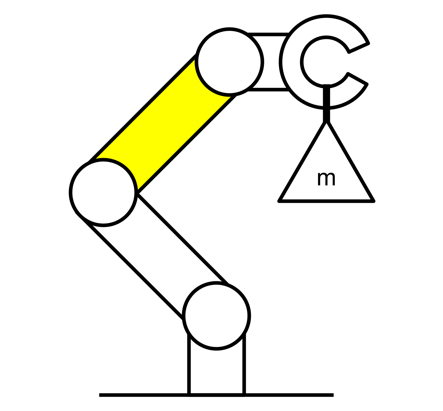
We’ve been given a few requirements:
- The mass of the component must be minimized at all costs.
- The length of the link must be 300 mm.
- The maximum allowed deflection (caused by the component) is 1 mm.
- The combined mass of the maximum payload and end-effector is 30 kg.
- The combined center of mass of the payload and end-effector is 50 mm from the joint.
- Both the base and end-effector joints can rotate in any axis.
We are allowed to assume that the arm does not move dynamically, so that our analysis can be static-only.
So how do we optimally design this component?
Abstraction
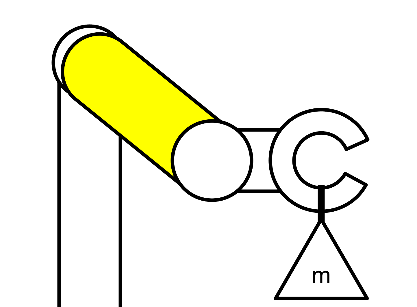
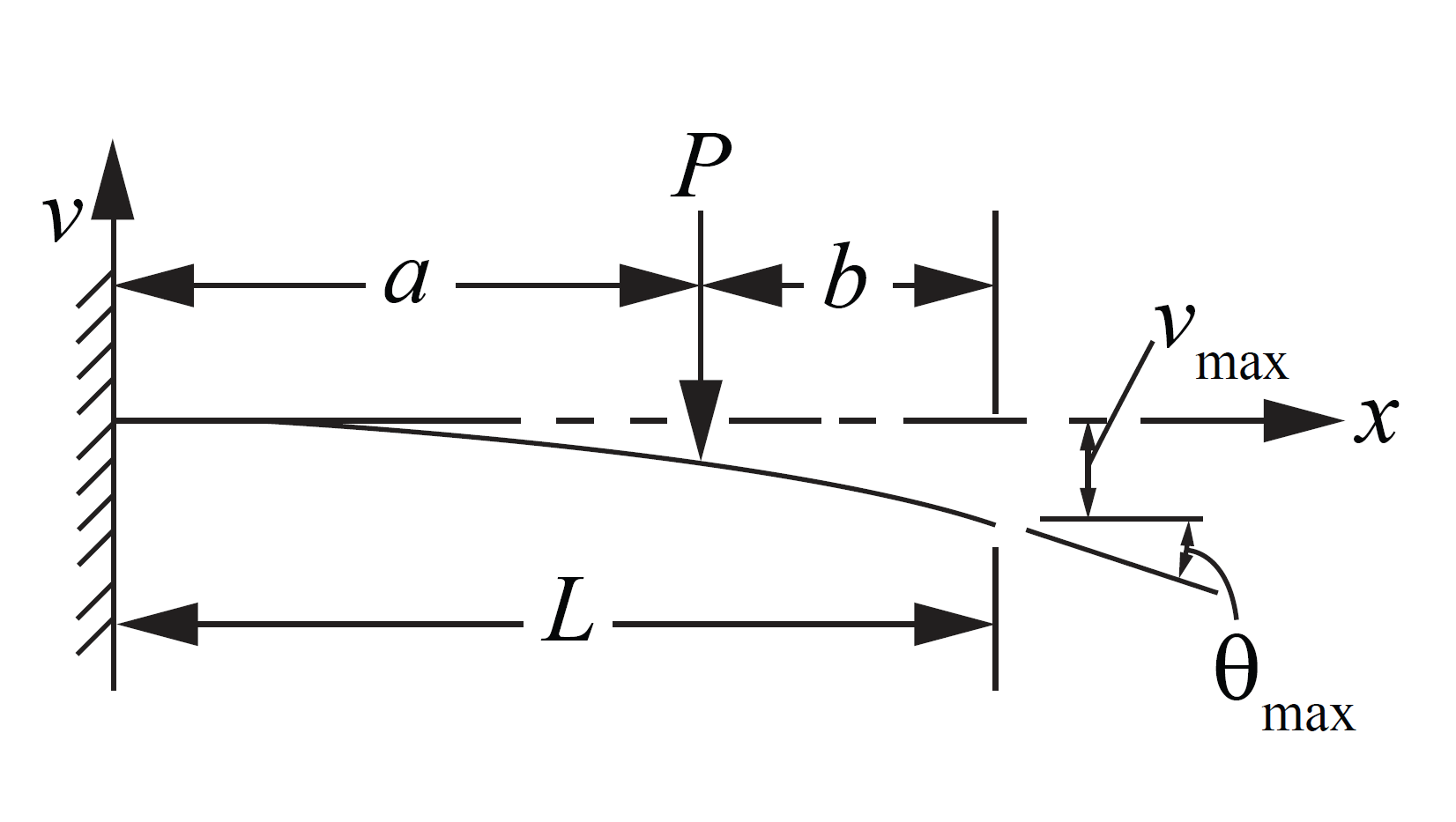
Let’s start by simplifying the situation by only looking at the worst-case scenario, as shown. In this case, maximum bending moment will be acting along the length of the arm and maximum torsion will be acting on it in the axial direction.
Let’s redraw it as a cantilever beam.
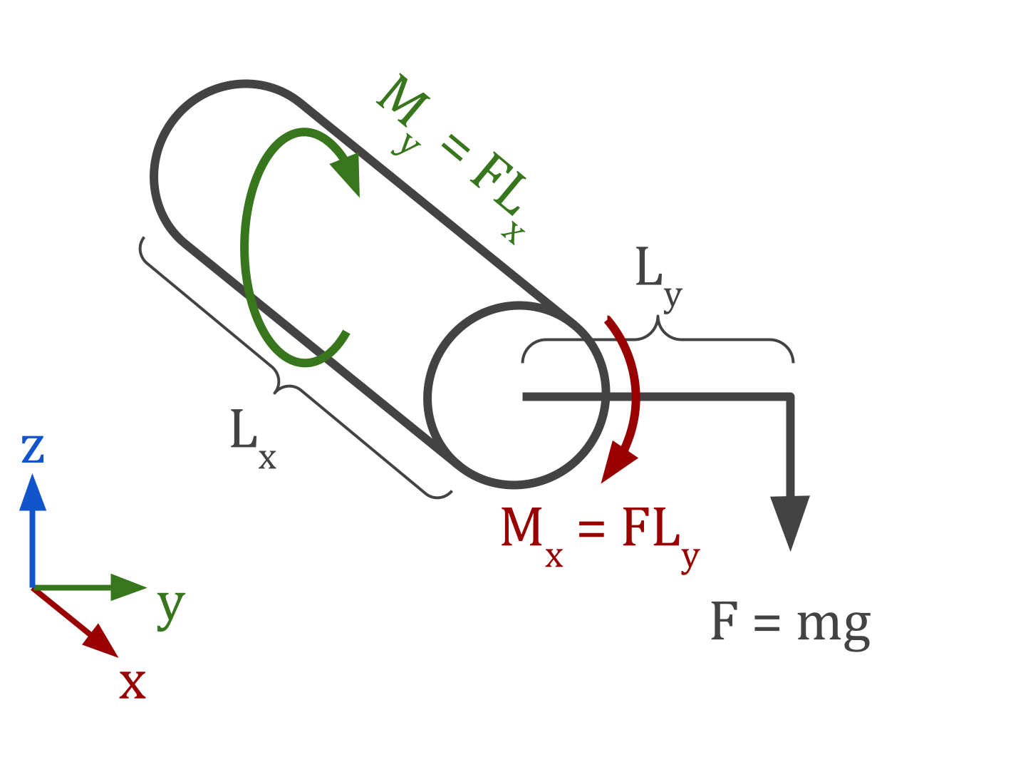
Remember what we know from the requirements:
- $L_x = 300 \text{ mm}$
- $L_y = 50 \text{ mm}$
- $m = 30 \text{ kg}$
Choice of Cross-Section
Choosing the cross-sectional shape of a cantilever beam is all about maximizing your second moment of area, a major determining factor in both stiffness and strength. On the other hand, you’ll also want to minimize cross-sectional area to ensure that the mass of the beam is as low as possible.
How do we maximize second moment of area while minimizing cross-sectional area? Well, second moment of area can be maximized by locating as much of the shape as far away from the neutral axis as possible, whereas area can be minimized by squeezing that shape into a thin band.
When bending is expected to occur in only one axis, the best solution is an I-beam. But because this section of the arm has powered rotation about its longitudinal axis, the beam must be able to support an equal load in any direction perpendicular to its length. As such, the cross-sectional shape of choice is a hollow circle, which has the best ratio of second moment of area to area when considering any neutral axis angle.
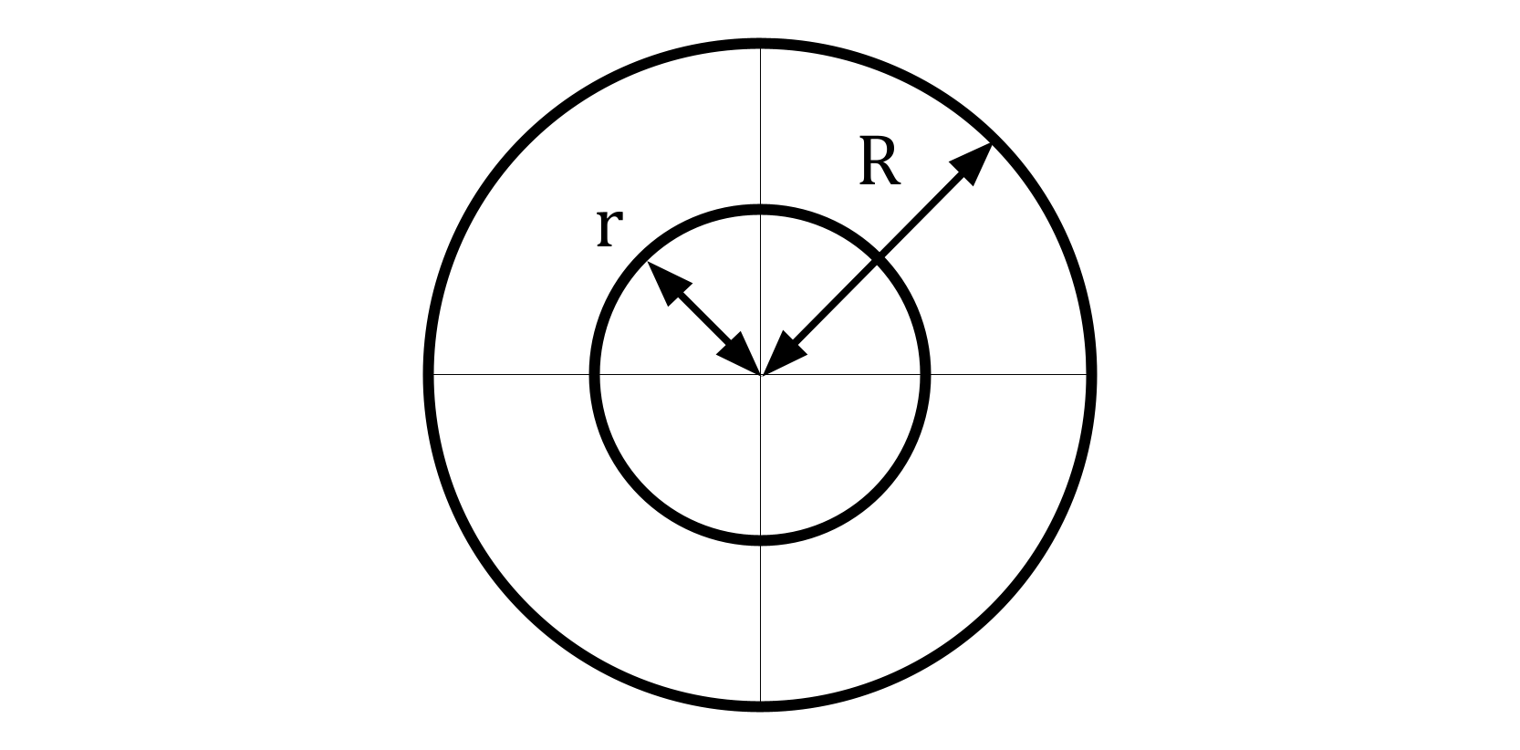
Area of a hollow circle: $$ \begin{equation} A = \pi(R^2 - r^2) \end{equation} $$
Second moment of area of a hollow circle: $$ \begin{equation} I = \frac{\pi}{4} (R^4 - r^4) \end{equation} $$
Second polar moment of area of a hollow circle: $$ \begin{equation} J = \frac{\pi}{2} (R^4 - r^4) \end{equation} $$
Equations
Now that we’ve simplified the problem down to a cantilever beam with a hollow cylindrical cross-section, we can use several equations that will describe deflection and stress acting on the system.
Shear Stress
Max shear stress for a beam with a thin-walled tube [1] $$ \begin{equation} \tau_{beam, max} = \frac{2 F}{A} = \frac{2 F}{\pi (R^2 - r^2)} \end{equation} $$
Shear stress due to torsion for a circular shaft [1] $$ \begin{equation} \tau_{torsion} = \frac{M_x R}{J} = \frac{F L_y R}{\frac{\pi}{2} (R^4 - r^4)} \end{equation} $$
Combining the two to get overall max shear stress: $$ \begin{equation} \tau_{max} = \tau_{torsion} + \tau_{beam, max} \end{equation} $$
Tensile Stress
Max tensile stress for a beam due to bending [1] $$ \begin{equation} \sigma_{max} = \frac{M_y c}{I} = \frac{F L_x R}{\frac{\pi}{4} (R^4 - r^4)} \end{equation} $$
Deflection
Deflection of a cantilever beam due to a force on the tip [2] $$ \begin{equation} \delta_{max} = \frac{F L_x^3}{3 E I} = \frac{F L_x^3}{3 E \frac{\pi}{4} (R^4 - r^4)} \end{equation} $$
Optimization
To evaluate this problem holistically, I’ve characterized it as an optimization problem. Our objective is to minimize the cross-sectional area (which is proportional to $R^2 - r^2$) as a function of $R$ and $r$.
$$ \begin{align} \min_{R,r} \quad & R^2 - r^2 \\ \textrm{s.t.} \quad & \frac{F L_y R}{\frac{\pi}{2} (R^4 - r^4)} + \frac{2 F}{\pi (R^2 - r^2)} - \tau_{max} \leq 0 \\ & F L_x R - \frac{\pi}{4} (R^4 - r^4)\sigma_{max} \leq 0 \\ & F L_x^3 - 3 E \frac{\pi}{4} (R^4 - r^4)\delta_{limit} \leq 0 \\ & r - R + t_{min} \leq 0 \\ & 0.01 \leq R \leq 0.075 \\ & 0.01 \leq r \leq 0.075 \end{align} $$Where:
- $t_{min}$ is the minimum thickness chosen by the user.
- (10) is the shear stress constraint.
- (11) is the bending stress constraint.
- (12) is the deflection constraint.
- (13) limits the minimum wall thickness.
- (14) and (15) define the min/max dimensions.
But before we can see how this performs, we need to choose the material.
Materials
Let’s look at three of the most popular materials when it comes to lightweight structural design: titanium, aluminum, and CFRP. There’s a reason these are the top three: strength-to-weight ratio, AKA specific strength.
| Material | Young’s Modulus (Pa) | Shear Str (Pa) | Yield Str (Pa) | Density (kg/m^3) |
|---|---|---|---|---|
| Annealed Grade 5 Titanium | 110e9 | 600e6 | 910e6 | 4430 |
| Aluminum 7075-T6 | 70e9 | 330e6 | 480e6 | 2710 |
| CFRP Tube, 0/90 Ply | 132e9 | 102e6 | 1745e6 | 1522 |
Bear in mind that there CFRP comes in many flavors: different ply orientations, grades of fabric quality, types of epoxy, and fabrication methods. As such, there can be an absolutely staggering amount of variation in material properties between one CFRP product and the next. For simplicity, I am choosing one particular product, a commonly used CFRP tube from Dragonplate.
We also need to be extra careful when making theoretical predictions about composites because of their anisotropy. In metals like titanium and aluminum, the yield strength and Young’s modulus are basically identical in every direction. But, for example, in CFRP the compressive modulus can be as low as 1/10th of the tensile modulus in some cases. What does this mean for a CFRP beam in bending? Well, a beam in bending is partially in tension and partially in compression, so its equivalent Young’s modulus and yield strength are some combination of the composite’s tensile and compressive moduli and strengths. This is known as flexural modulus and flexural strength, which is what we should be using here. Furthermore, we should be careful to choose the modulus and strength ratings for the correct ply orientation; in this case 0 degrees.
As for minimum wall thickness, I found that deciding on $t_{min}$ was very tricky. In the end, I went with the pragmatic approach of checking the minimum tube thicknesses available online for each material. For titanium and aluminum, that’s 0.4064 mm (~1/64"), whereas for CFRP it’s 0.762 mm (~0.03").
Note that in the real world, risk of impact to the sides of the tube may drive your required wall thickness up.
Results
I used NLOPT, a library for nonlinear optimization, to solve the aforementioned optimization problem. The code can be found here.
| Material | R (mm) | r (mm) | Thickness (mm) | Mass (kg) |
|---|---|---|---|---|
| Annealed Grade 5 Titanium | 34.357 | 33.972 | 0.385 | 0.110 |
| Aluminum 7075-T6 | 39.463 | 39.063 | 0.400 | 0.0798 |
| CFRP Tube, 0/90 Ply | 26.442 | 25.722 | 0.719 | 0.0538 |
Analysis
After looking at the equations from earlier, one’s first impression might be that the cylinder radius should jump to the maximum radius possible. This is not the case, because doing so would enlarge the cross-sectional area (and therefore mass) unnecessarily. Instead, it’s all about minimum wall thickness. As an example, optimizing inner and outer radii given a specified minimum wall thickness:
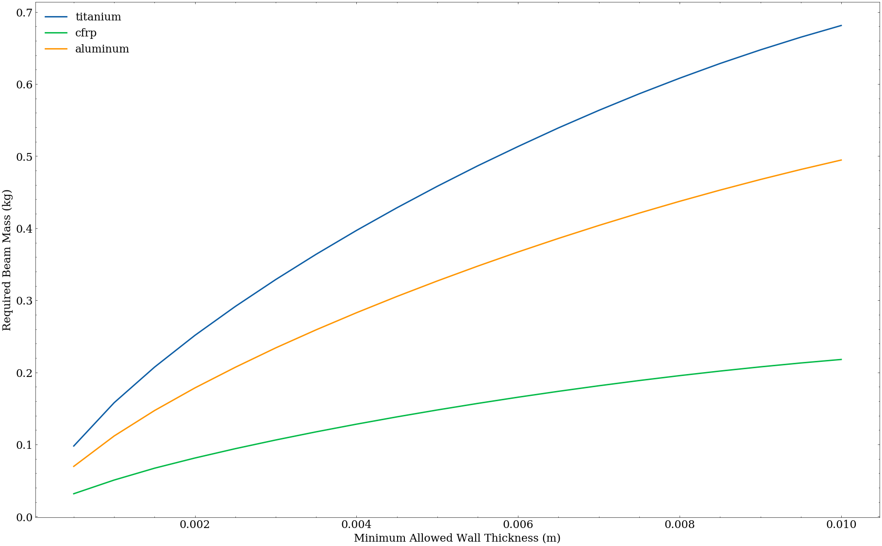
As previously mentioned, you want to squeeze your geometry into as thin of a band as possible to take advantage of the second moment of area without using up too much cross-sectional area.
Note that if minimum wall thickness were no object (i.e. you could have infinitesimal walls), then the optimal choice would be to maximize your radius! Sadly, we live in the real world, where we have to care about manufacturability or fabricatability.
With the given boundary conditions, the deflection limit is the next deciding factor after minimum wall thickness. As an example, optimizing inner and outer radii given a specified maximum deflection:
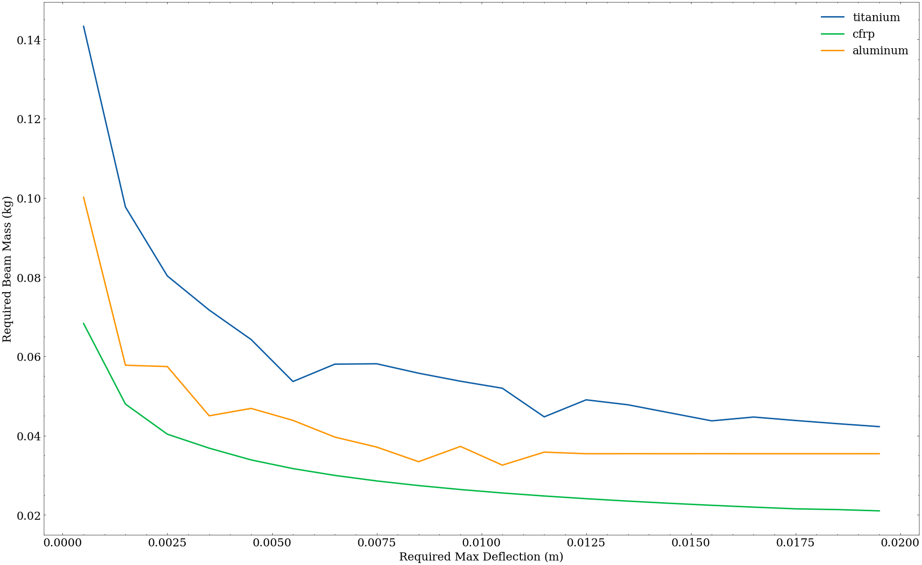
Of course, if the deflection limit is high enough, it becomes irrelevant and the shear and tensile stresses become more important.
Size vs. Strength
I have to admit that I was initially left scratching my head after looking at these plots. After all, why would the optimal titanium beam be heavier than the optimal aluminum beam if the specific strength of titanium is greater?
Recall Equations (5) through (8): the torsional stress, tensile stress, and deflection are all inversely proportional to the 4th power of the radius.
$$ \begin{align*} \tau_{torsion} \propto \frac{1}{R^4} \end{align*} $$ $$ \begin{align*} \sigma_{max} \propto \frac{1}{R^4} \end{align*} $$ $$ \begin{align*} \delta_{max} \propto \frac{1}{R^4} \end{align*} $$On the other hand, area (and therefore mass) is proportional to merely the 2nd power of the radius.
$$ \begin{align*} A \propto R^2 \end{align*} $$This means that with increasing radius, stress and deflection drop faster than mass increases!
Now, does this mean we should just 3D print everything out of foaming PLA? In most cases, absolutely not! First of all, keep in mind that this relationship only holds in situations where second moment of area is important. For example, in bending or buckling as opposed to pure compression or tension.
In addition, you will usually have more stringent constraints on the bounding box of the design, and once your maximum radius is sufficiently limited, the material with the higher specific strength will win.
For example, optimizing for inner radius $r$ only given a specified maximum outer radius $R$:
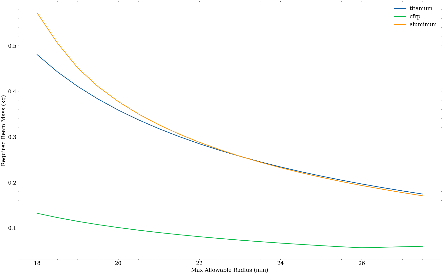
You can see here that second moment of area dominates the beam moment problem overall, but for sufficiently low $R$, titanium wins.
So second moment of area can be more important than specific strength… provided you have the space to exploit it.