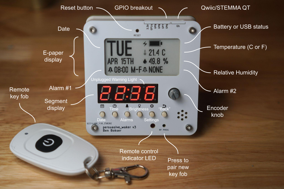
So I made my own alarm clock.
It has no snooze button and no off button. It also has a backup battery in case it gets unplugged, and there’s no way to remove the battery without a hex key.
Actually deactivating the alarm requires hitting a remote key fob. The idea is to hide the key fob as far away from your bed as possible. Obviously this is more effective the larger your home is.
To close loopholes, you also can’t change the alarm or even the date or time without hitting the remote switch.
Details
 |
|---|
| Schematic. It’s in vector format, so you can zoom way in. |
A quick list of features:
- Time, date, and two alarms
- Humidity and temperature display
- LED brightness setting
- Celsius vs Fahrenheit setting
- STEMMA-QT/Qwiic breakout
- 2.54mm pitch breakout with 3.3V, GND, 5x GPIOs, and 3x ADC
The microcontroller is an RP2040 and the code is written in CircuitPython. I found CircuitPython simultaneously really convenient and extremely limiting.
The github repo is here if you want to learn more. It’s fully open source. Electrical (KiCAD), mechanical (STEP), and software.
The Story
At first, this was just something I wanted for myself, and so I cobbled something together out of parts I had lying around. That was the V0. Then I decided to do a PCB, and made the V1. The V1 had a bunch of issues, but the V2 functioned the way I wanted it to.
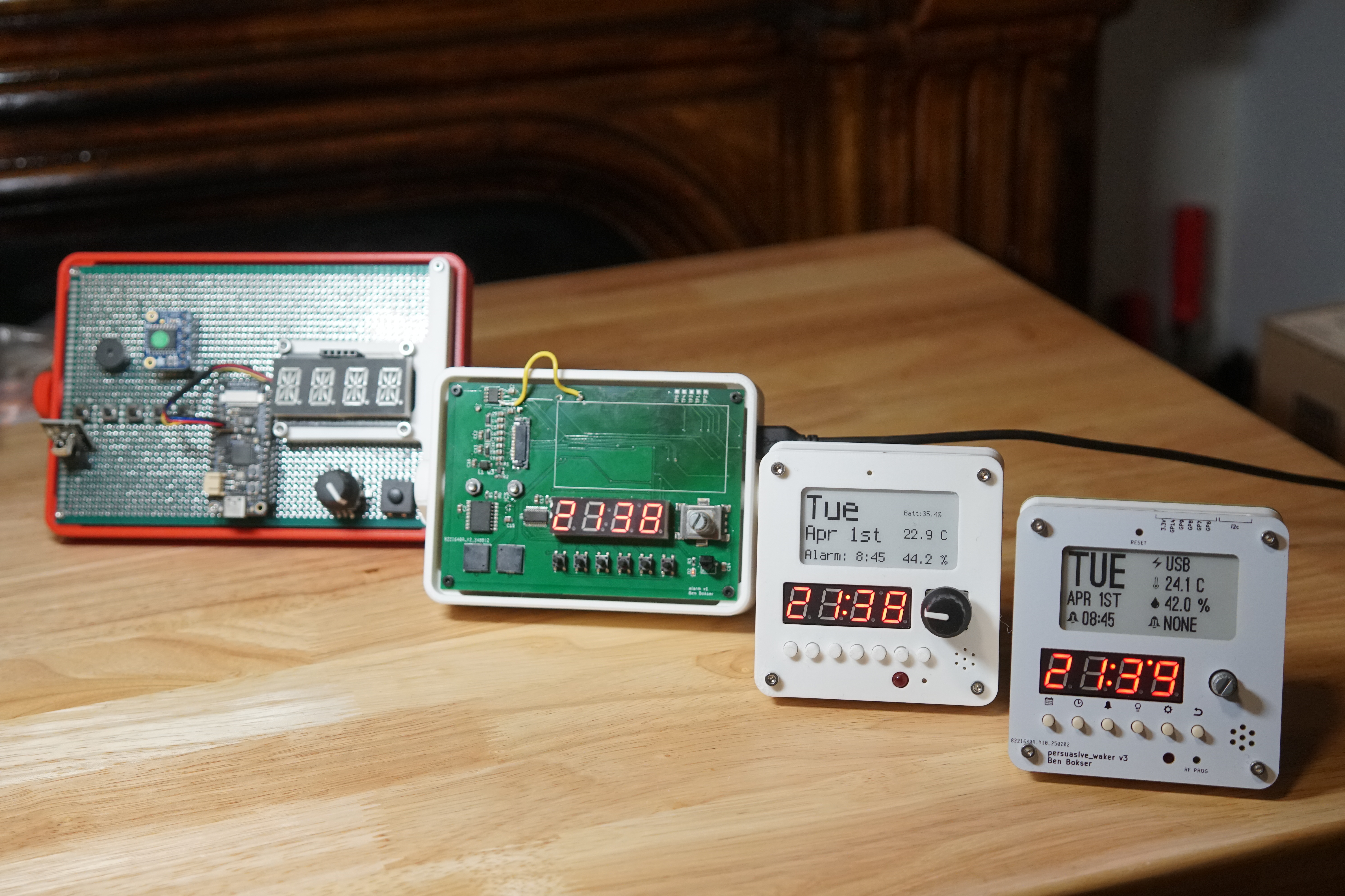
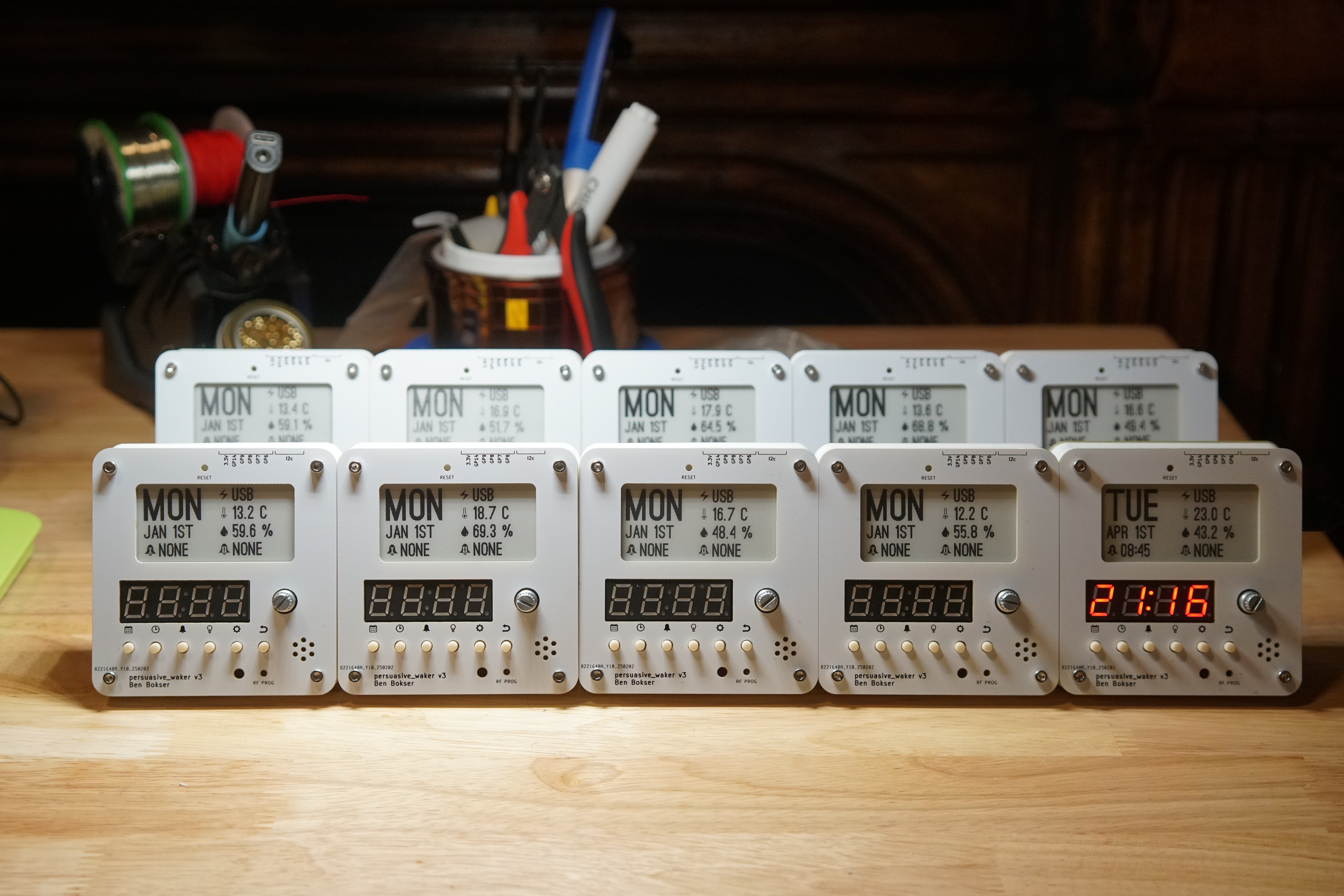
I liked the V2 so much that I wanted to share the design with my friends. So I decided to make 10 of the V3, with the intent of giving them out to people I knew.
This turned out to be a lot more trouble than I had anticipated.
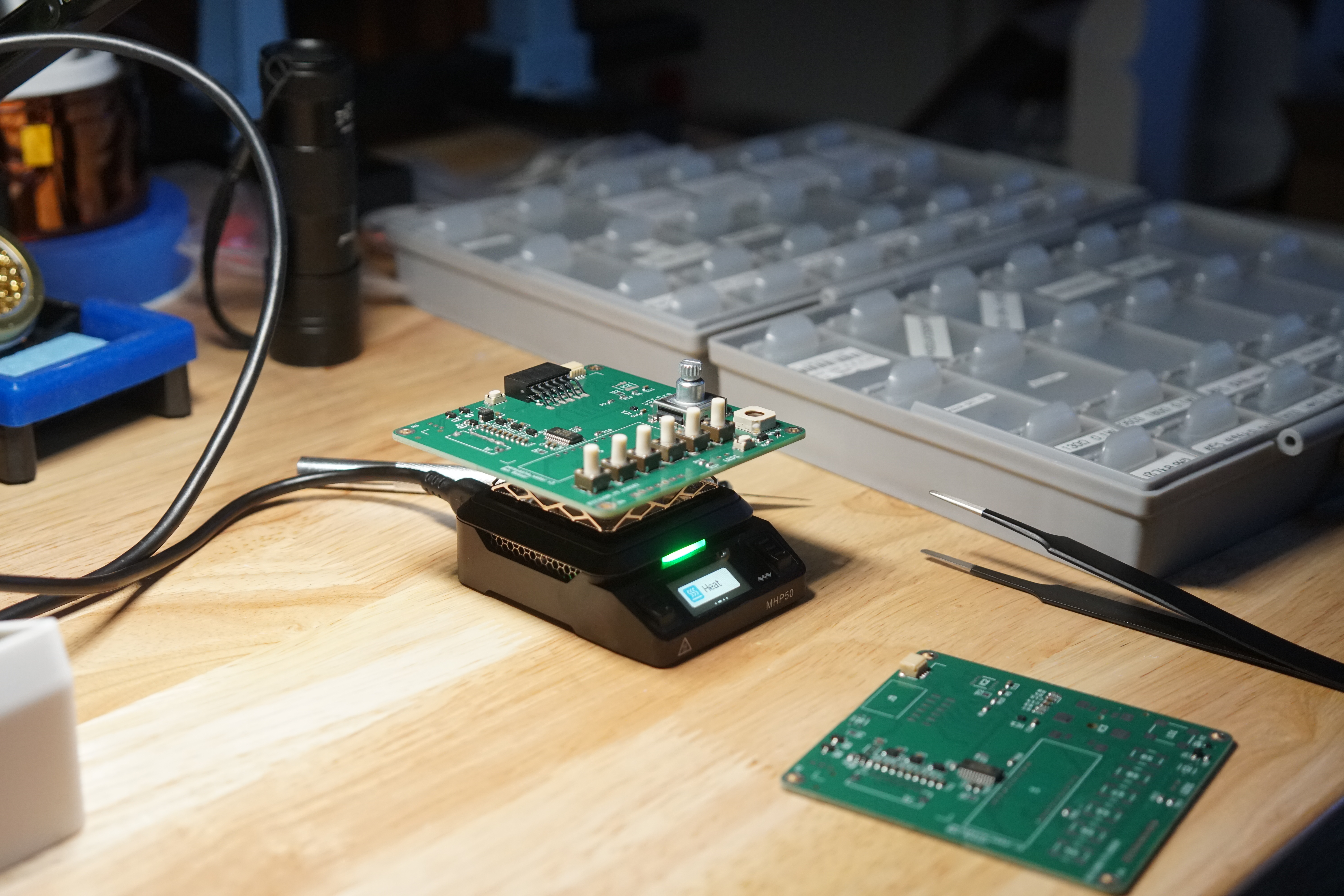
First off, I didn’t want to deal with JLCPCB’s annoying MOQ requirements for PCBA–they were going to force me to buy way more parts than I needed (and their weird consignment system seemed like overkill)–so I only had the boards ordered with the “basic” components assembled (mostly just resistors and caps). This ended up being the worst of both worlds. I was ordering PCBA but also tediously soldering every board. Would not recommend.
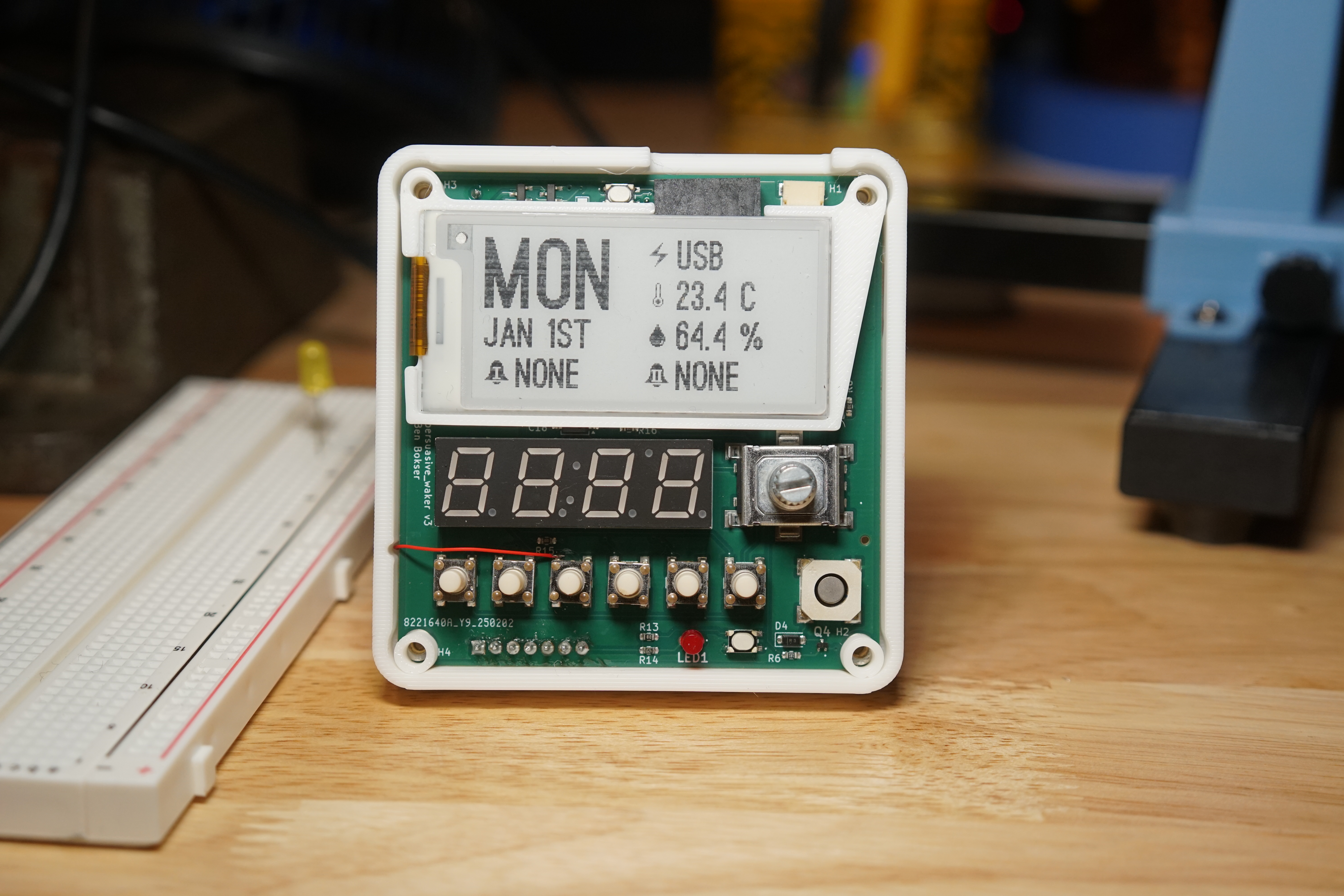
Then it turned out I had accidentally shorted one of the pushbuttons in the schematic. This had to be fixed with Kynar wire on all ten V3s. You can see that in the open shot below.
Next, I found out that one of the battery holders had arrived with the positive and negative terminals on its connector reversed. What the heck! I didn’t discover this until I had already plugged it in. Fortunately, the design includes reverse voltage protection.
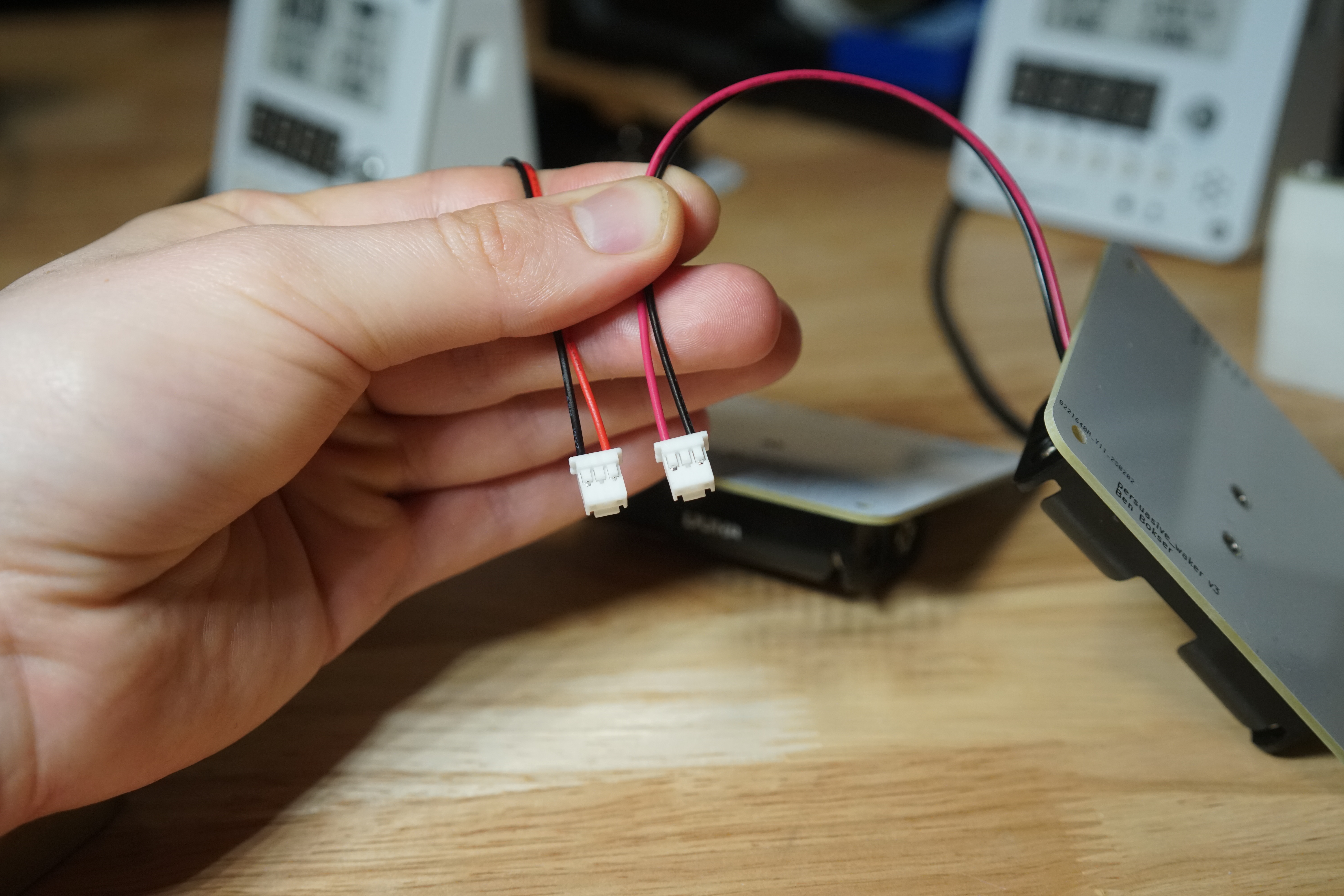
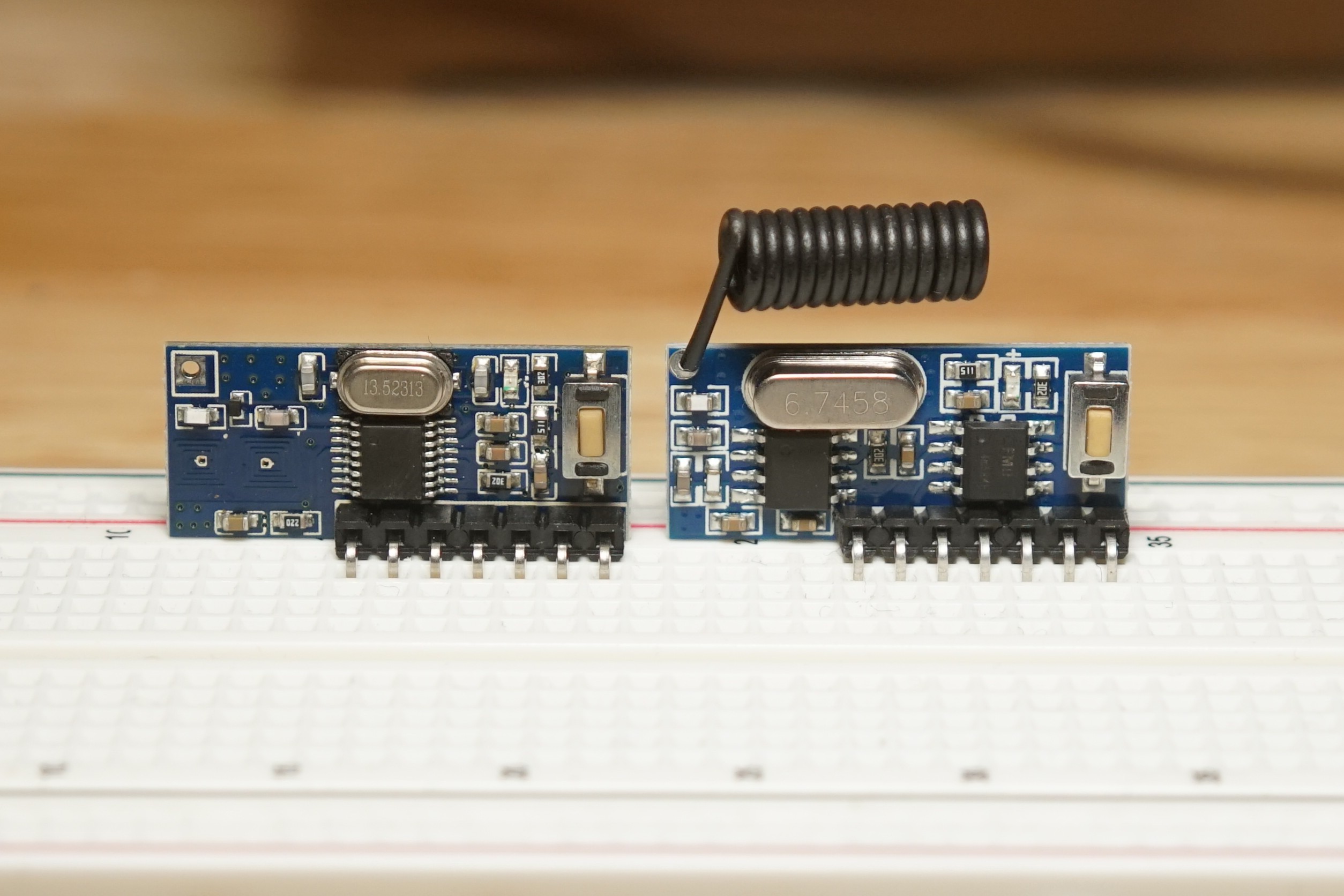
Finally, when I thought the ordeal was over, half my RF receivers bricked on the same day. It turned out that they were knockoffs–I had naively ordered them from AliExpress rather than the official website. They don’t even look the same. Outrageous!
Anyway, it’s finished! And now I get to ship these out to my friends.
Last edited 2025-08-04.